HBE-Comm

Testing For easy understanding of Basic Communication Engineering

  • Observation of Communication Waveform using Oscilloscope and Waveform Generator
  • Modularization by Communication Themes
  • 2 channel Digital Oscilloscope
  • 8 channel DAQ
  • Basic Circuit of Analog Communication and Digital Communication
  • Test using Bread Board

Introduction

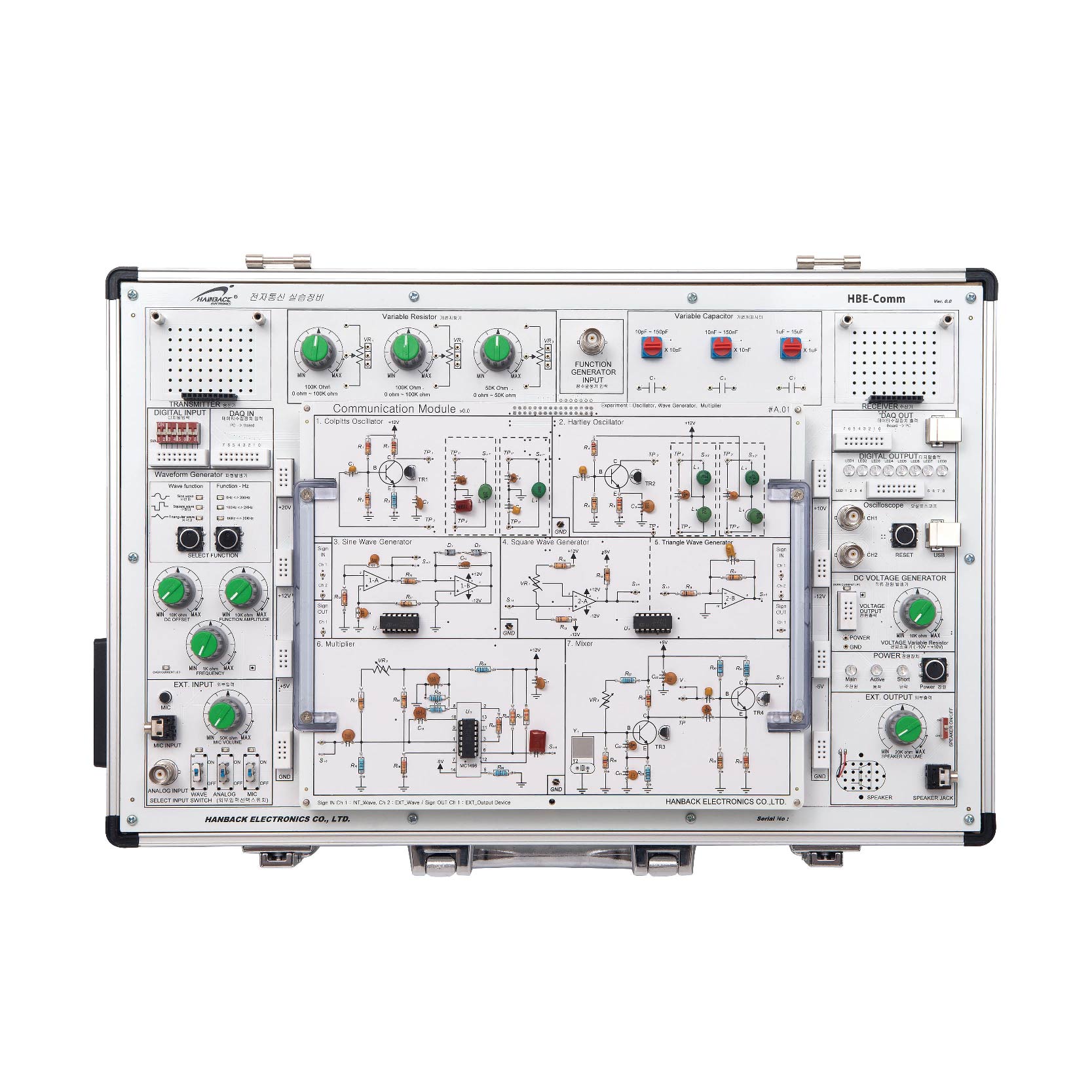
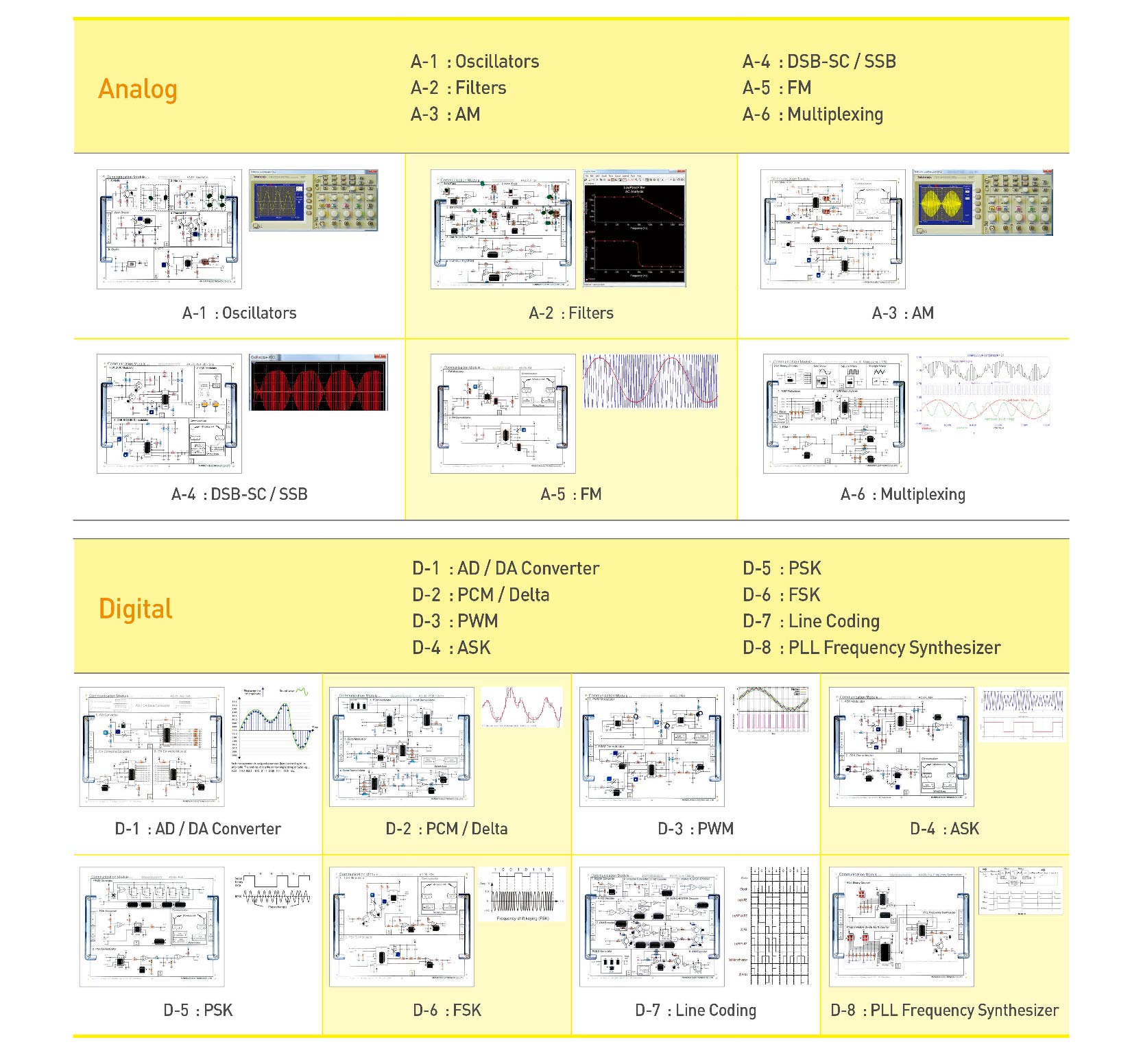
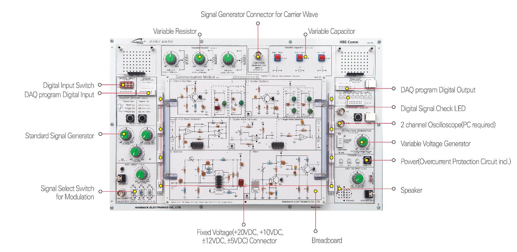
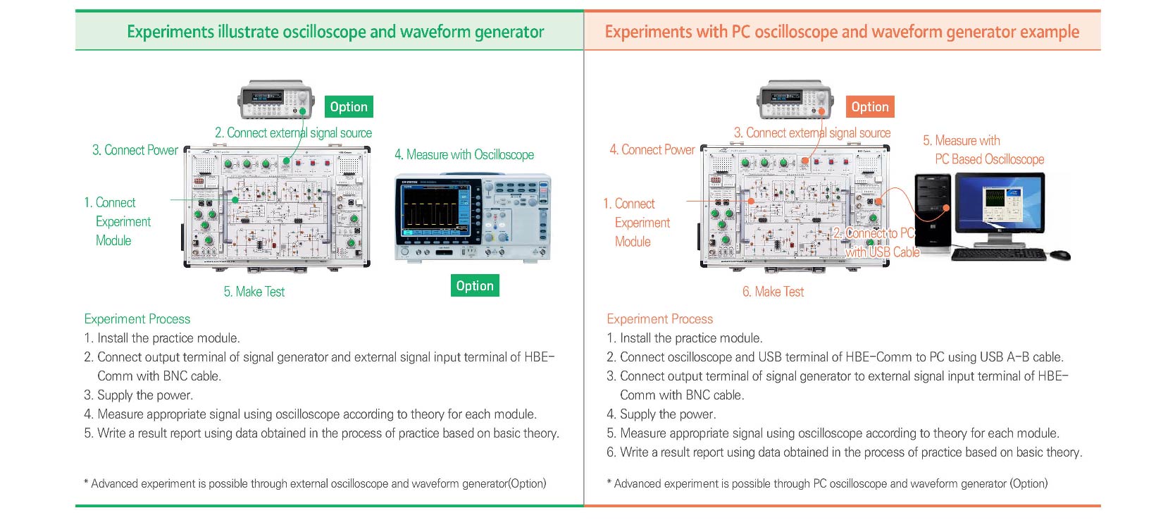
For basic communication, we can understand Signal Generator, Frequency Multiplier, and Filter and then we can know the basic circuit of Analog Communication and Digital Communication. This is the basic Education Theme of Communication Engineering used in Educational Field for a long time. HBE-Comm arranges the basic circuit as drawn on Circuit Diagram to understand it easily, and this uses generates Carrier Signal with Waveform Generator and inputs it to the circuit and also uses Oscilloscope to see
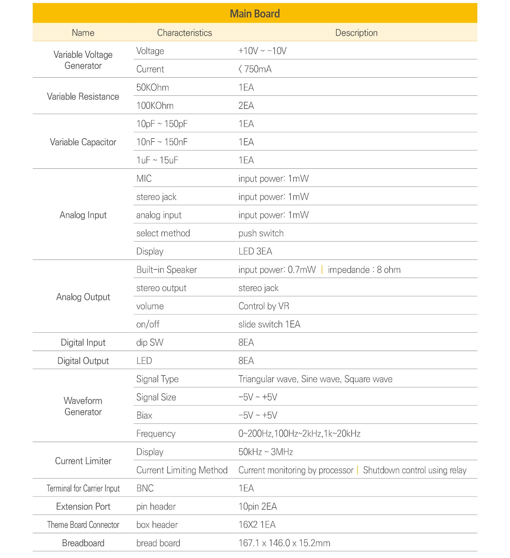
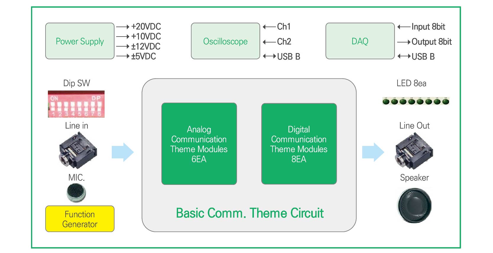
the waveform of main parts. Then, we can know how to use Waveform Generator and Oscilloscope. For Education Course, basic communication equipment includes Basic Circuit, Analog Communication, Digital Communication and Application Communication and each communication has own Module. So we can start Test immediately after mounting Module to the equipment. Application Circuits of AM receiver and FM receiver are added in order to understand how the public airwaves is received. This provides BreadBoard and Ext.Power so we can make other communication circuit with it

Features

  • Test uses Measuring Equipment so it is possible to understand how to use Measuring Equipment.
  • Module by Themes are provided from Basic Circuit to Application Circuit for communication.
  • 2 channel Digital Oscilloscope and PC programs are provided basically.
  • 8 channel DAQ is provided as Hardware and PC software is provided in order to design digital data for circuit and check data from circuit. 
  • Test Point is provided for easy contact of Probe to a part for measurement.
    It is possible to provide Standard Waveform, Microphone and Line-in selectively to communication circuit.
  • We can listen to received signal with one of Head Phone and embedded speaker.

Configuration and Names

1. Additional Option Connector
2. Digital Input Switch
3. DAQ program Digital Input
4. Standard Signal Generator
5. Signal Select Switch for Modulation
6. Variable Resistor
7. Signal Generator Connector for Carrier Wave
8. Variable Capacitor
9. Additional Option Connector
10. DAQ program Digital Output
11. Digital Signal Check LED
12. 2 channel Oscilloscope(PC required)
13. Variable Voltage Generator
14. Power(Overcurrent Protection Circuit incl.)
15. Signal Output
16. Fixed Voltage(+20VDC, +10VDC, ±12VDC, ±5VDC) Connector
17. Breadboard

Block Diagram

Experiment Examples

Product Specifications

Theme Modules

– Analog Communication Theme Modules

– Digital Communication Theme Modules

Training Contents

Learning HBE-Comm Practice basic communication

1st week. Oscillator
2nd week. Filter
3rd week. Amplitude Modulation
4th week. DSB-SC / SSB
5th week. Frequency Modulation
6th week. Multiplexing
7th week. AD/ DA Conversion
8th week. Pulse Code Modulation / Delta Modulation
9th week. Pulse Width Modulation
10th week. Amplitude Shift Keying
11th week. Phase Shift Keying
12th week. Frequency Shift Keying
13th week. Line Coding
14th week. PLL Frequency Synthesizer

Product Configuration