Modular Integrated Training System Microcontroller
- Supports multiform MCU of independent module structure
- Supports CPLD module for digital circuit experiment
- Functional modularity of application
- Provides analysis and measurement module for improving the efficiency of MCU learning
- Supports various interfaces for signal connections between MCU and module
- Offers measurement point for signal analysis
- Provides multiform program experiments for the basis and project experiments
Introduction
MCU products based on 8-bits is the basic training theme that is being used on education sites for a long time. However, when it is a product manufactured to fit into traditional training method, a cramming one, it is impossible to configure its capabilities in the way users want, This product is a micro embedded training system designed to support variety of MCUs and, based on that, realize independent modularity of each function for the purpose of quickly applying the multiform program lessons including the basic training and meeting user’s requirements to effectively apply the creativity engineering training recently emerging from universities and high schools to education.
Features
- Devices of ATmega128, 89C51, PIC18F6722 designed to be modules of connector structure which are mountable and removable, allowing multiform microcontroller training.
- CPLD module installed to perform the digital circuit design education at the same time.
Provides a configuration that multiform connects MCU module and functional module. - Each functional module can be installed and removed so users can use application design type they want by utilizing functional modules separated from the base board user wants.
- Provides the signal and power analysis modules that can improve the efficiency of MCU lesson and design.(interrupt, frequency analysis)
- Provides the dedicated measurement point for easy analysis of MCU and application signals.
- Provides multiform input switches and output display devices.
- Multiform sensor modules are mountable.
- Provides application modules for USN and sensor training.
- Provides various experiment programs necessary for application experiment.
- Supports multiform design environment ranging from the basic processor education level to the application design level.
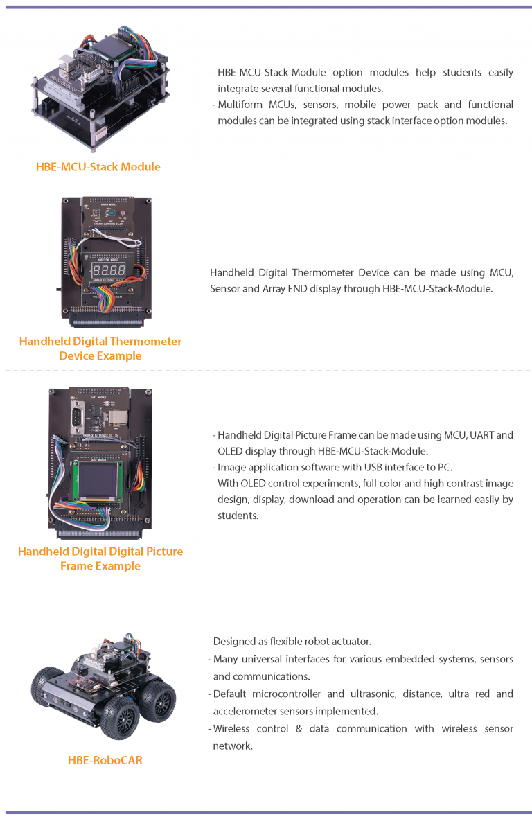
- Provides multiform option modules such as stack module and actuator module for maximizing use of the product.
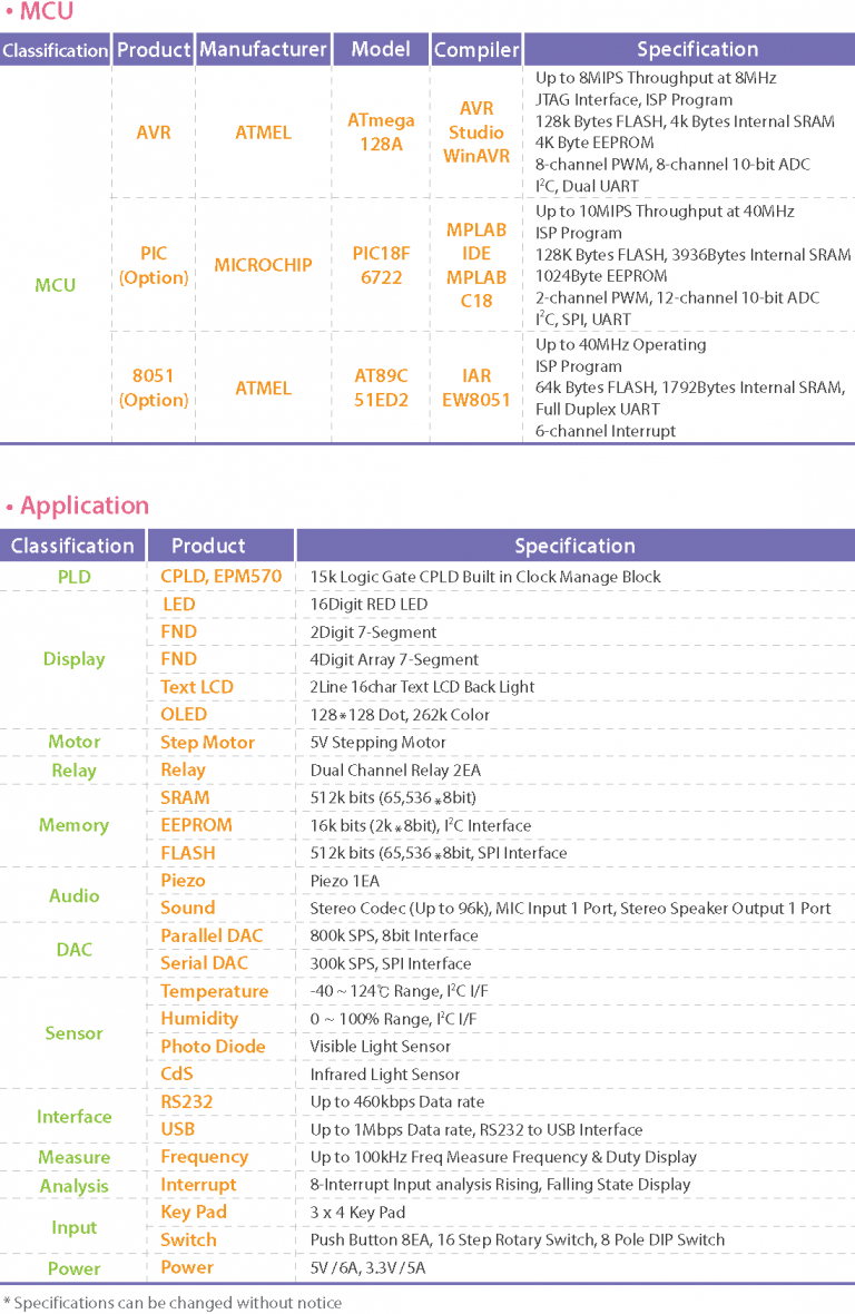
Product Specifications
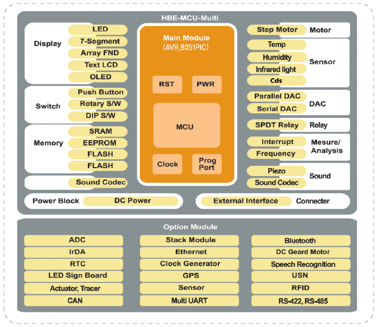
Block diagram
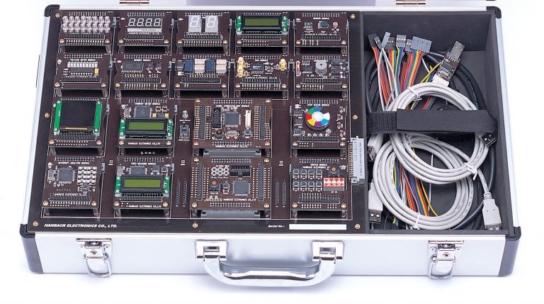
Main configuration
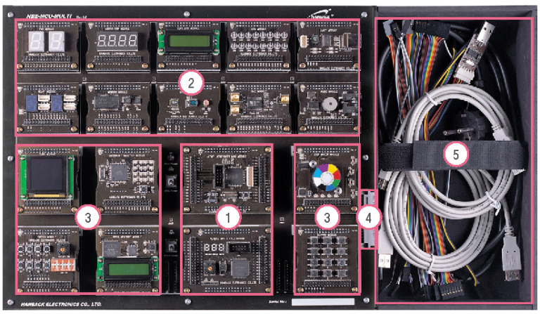
1. MCU Module Zone : MCU and CPLD Module
2. 56mm *45mm Module Zone : LED, FND, Array FND, Text LCD, Sensor, Memory, Relay, DAC, Audio, UART Module
3. 56mm *60mm Module Zone : OLED, Step Motor, Switch, Key Pad, Freq Measure, Interrupt Analysis Module Installation
4. Option Module Interface : Interface for connecting option modules additionally provided
5. Cable box : Contains various cables used for the product
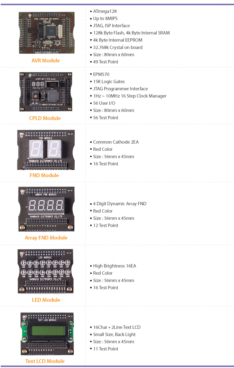
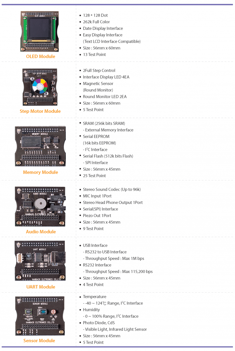
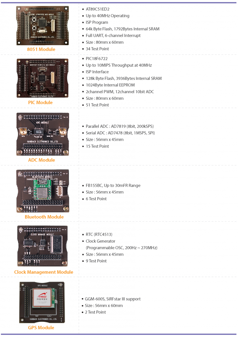
Module Specifications
Basic Modules
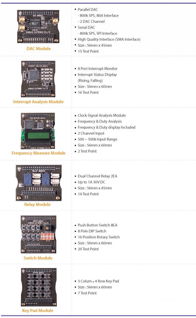
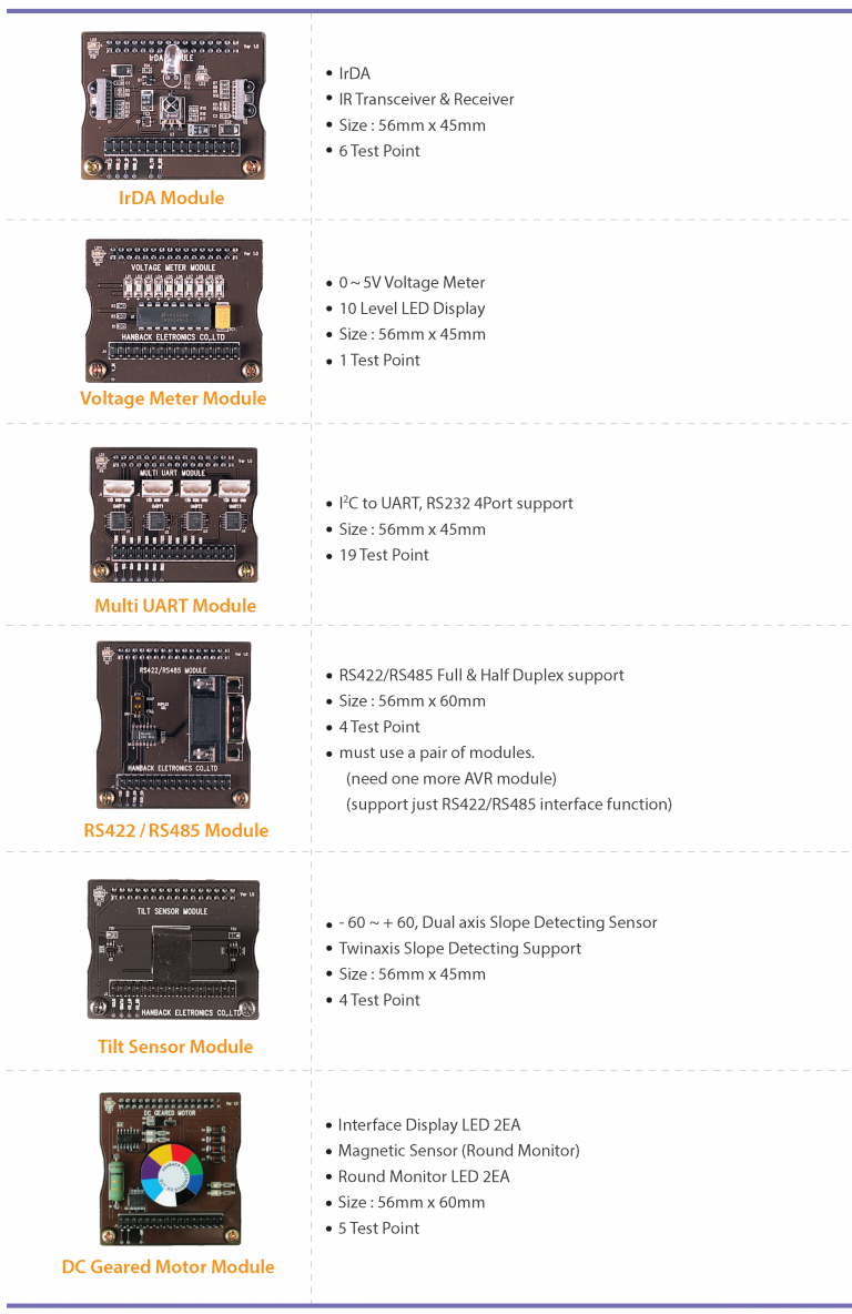
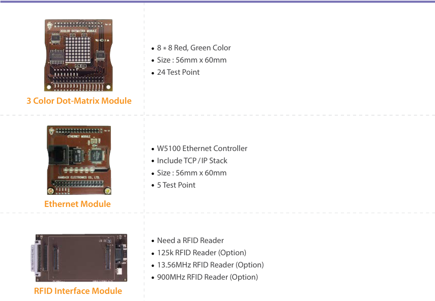
Option Modules
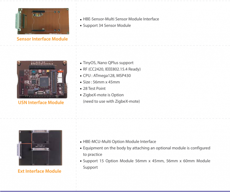
Application Modules (Option)
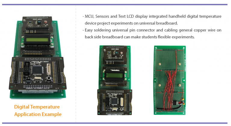
Application Examples
All kinds of modules of HBE-MCU-Multi can be used for the application of universal breadboard.
Training Contents
HBE-MCU-Multi(AVR)
OVERIEW OF MICROCONTROLLER
1. AVR Micro Controller
2. AVR Micro Controller Development Environment
FUNCTIONS OF MICROCONTROLLER
3. GPIO I/O Control
4. Internal Memory
5. Interrupt
6. Timer and Counter
7. Timer and PWM
8. UART
9. A/D Converter
10. External Memory Interface
11. Serial Interface
USING MICROCONTROLLER
12. Rotating Step Motor
13. Pin Pad using KeyPAD
14. LED brightness control using DAC function
15. Digital frame using OLED
HBE-MCU-Multi(8051)
OVERVIEW OF MICROCONTROLLER
1. 8051 Micro Controller
2. 8051 Micro Controller Developing Environment
FUNCTIONS OF MICROCONTROLLER
3. GPIO I/O Control
4. Internal Memory
5. Timer and Counter
6. Interrupt
7. PCA and PWM
8. UART
9. External Memory Interface
10. Serial Interface
USING MICROCONTROLLER
11. Rotating Step Motor
12. Pin Pad using KeyPAD
13. Controlling LED brightness with DAC
14. Make Paint with OLED
HBE-MCU-Multi(PIC)
1. PREPARING TEST AND USING MPLAB
2. TURNING ON LED
3. RECEIVING PORT INPUT
4. STATIC FND
5. DYNAMIC FND
6. INPUTTING SEVERAL SWITCHES(KEYPAD)
7. DISPLAYING CHARACTERS ON TEXT LCD
8. RECEIVING EXTERNAL INPUT OF TIMER/COUNTER
9. INTERRUPT
10. STEPPING MOTOR
11. PWM
12. UART COMMUNICATION
13. ADC
14. EEPROM
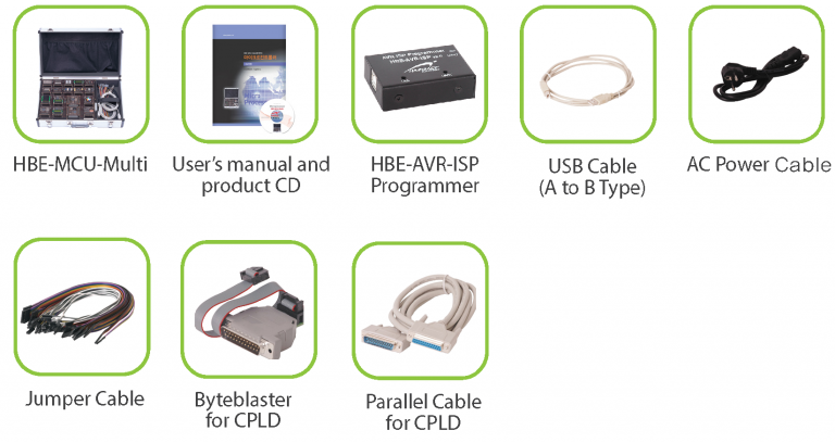
Product Configuration